C64 Audio Issues

C64 No Audio

Picked up a totally sweet SD2IEC board which allows emulation of the Commodore floppy drive from a SD card. It’s similar to the SIO2SD boards that do a similar function for the Atari family of home computers, except for C64. After getting it hooked up and being fairly impressed with the unit I noticed that my C64 doesn’t have sound. The one thing the machine is known for — it’s missing.

First step was checking power supplies. Oddly I had a 2nd PSU on hand, swapped it in place and no go. The internet said it could be a culprit, this makes sense as the power supply has a DC line which would be used by the logic chips that make up the computer as well as an AC line which is commonly used for opamp ICs and stuff that has a +/- power feed. Anyhow the power supply checked out A-OK which doesn’t solve issue.

Next step was to open the thing up, and hunt. Looking online I found details where the SID chip was and the datasheet. Poking at the chip while a music disk / demo was playing I could see the address and data lines were busy so not decode logic or data bus buffers to the naked eye. The thing is the output side of the chip just sits at a high voltage so it seems toasted. I didn’t check the two external capacitors, maybe later. The thing is the SID chip is the value of the machine and places like eBay are full of fake copies from China that don’t function. So this one goes on the shelf until a parts machine turns up.

UPDATE 5/3/2917

Matt Crainer brought me a donor C64 that had already been robbed of it’s keyboard controller IC. I carefully de-soldered the SID chip. I didn’t have a 28 pin DIP socket on hand, and instead of ordering one I ordered some break-away SIP sockets. The quality of the machine pin holes was not up to that of what I would get from a mainstream commercial mail order house machined DIP sockets, but it was good enough. Soldered two 14 position sip sockets. I cleaned up the SID chip first, trying to remove any excess solder or burs on the pins, didn’t want them to bend on insertion. Threw it in. Powered on the C64. I googled for some hints as to how to get sound without digging out the SD drive emulator and found a post from VCF/MARCH forum I believe on some addresses to poke. Noise was heard! All is good. Buttoned it all up and this project is checked off!!!!

Picture added to slides above of soldered in SIP socket.

LED Video Screen Update, it’s done!

A little bit late on this post, but the screen was 100% before MAGFest 2017. 6 frames each containing qty 9 32 pixel x 16 pixel modules are complete. I want the metal ones like the rental screens, but in the meantime it will suffice! The screen is 3 meters wide by 1 meter high, or can be setup as 6 meters wide by 1/2 high. I have the drivers on hand to split it into 2 or 3 separate units as well.

Power consumption can hit 12 amps. There is 480 amps of 5V power behind the screen. 4 modules have color issues (very red), I have spares but have yet to swap them.

LED Expansion 3

QSC BASiS / QSC Dataport to XLR adapters

MAGFest was approaching and I found a sweet deal on a few QSC BASiS units. For the record, I love QSC hardware. I’ve owned a few Digital Cinema amplifiers for many years, as well as a CX series. My goal back then was to have the THX cinema certified amplifiers for my home theater, and at the time people weren’t so aware of eBay. The amplifiers did suffer an issue or two which I suppose can be the subject of another post. There is a service bulletin.

But back to the BASiS units. I was after some QSC units from their RAVE series that use an older standard called CobraNet. CobraNet does UDP broadcasts of audio packets, raw PCM uncompressed. The RAVE units that do analog tend to catch quite a bit more, but I stumbled onto the BASIS units which are meant to hook straight to the QSC amplifier dataports. The dataports are DB-HD-15 (think VGA) connectors that hook to management processors. Note – Don’t use a common VGA cable, all pins must be wired straight through and many VGA cables share grounds among a number of pins.

Doing some research online I found there is no issue making breakouts that go from DB-HD-15 to XLR or RCA, and QSC even sells a breakout board with screw terminals. Sweet!

The bad news? Didn’t get the network working enough in the MAGFest arcade in 2017 to get it working. Next event, and in the meantime I will use my BASIS boxes with my amps to run audio around the house. Once the network is segmented so that the broadcast traffic from the audio doesn’t cause the WiFi to fall over….

SGI Indigo R4K Failure – Let out the magic smoke! Burning smell

SGI Indigo Failure

So I *finally* managed to find the keyboard cable for my SGI Indigo on my last trip to Norfolk, VA. This completed what I needed: the 13w3 to VGA cable, the special keyboard and mouse, the system and the keyboard interconnect cable. I humped the thing onto my desk after clearing a bit of space, hooked it up to my monitor, then switched my first SGI on. It powered on! But then came this nasty smell. That’s not good! It did show the clock TOD error, no chime sound (just clicks.)

I originally bought the Indigo from Reputable Systems (Greg Douglas) in the 90s. I was working tech support at the time, living with my parents, and it cost a good chunk of cash — especially by todays standards. Originally it was R3K with a lower level graphics subsystem that I believe could do some hardware 3d acceleration but only 256 colors. I’ll admit when I first started messing with it I was a bit disappointed. It was still sort of slow, but had good audio capabilities and worked well as an X-term. It wasn’t long before MP3 was a new thing and the system couldn’t decode a 128kbps MP3 real time though, it took about 6 minutes for a 4 minute song — so I would have to write it out then write it to minidisc. Creative commons licensed music, of course.

Somewhere along the lines in my SGI fandom I think I ended up with a 9u VME frame that had an ELAN graphics boardset on it. I also ended up with a 2nd SGI Indigo from NASA auctions I used to frequent, one with the faster MIPS R4000 series CPU (R4K.) I remember posting that I was giving away a bunch of hardware including parts from the NASA Indigo, and left it and other stuff behind my office in Virginia Beach for someone else to pick up. But a homeless scrapper got to it first, taking everything metal and leaving plastic shards of laser printers and SGI Indigo (and other equipment) behind. Ugh.

But I held onto my Indigo, not having looked at the CPU cards in a long time. The first thing I did was pull out the CPU card and thought, “man this is bulkier than I remember! What a crazy heatsink for this slow R3000 processor.” But it turns out the R3K board isn’t a R3K board, it’s a R4K board. So then I’m thinking, “Okay so I guess I kept the R4K CPU and the lower graphics board.” But no, the graphics boardset looks stout. So I guess I kept both higher end parts and gave away the old R3K / Entry stuff. Or maybe the Entry graphics was in one of the bigger deskside systems on the frame the Elan came on. I can’t remember.

I remember that the Indigo had two power supply options. One for R3K/Elan graphics and one for R4K. I thought you could use a R4K with entry graphics on the weaker power supply as well. This was a huge issue in my mind since I figured my Indigo had the R3K PSU. I pulled the PSU from Indigo (My Indigo was always named Eggbert from a Super Mario Bros 2 character of similar name that was purple, so from here on it’s Eggbert.) So Eggbert’s PSU turns out to be the R4K model! I opened it up, the capacitors look okay but that really doesn’t say much. No burnt smell inside PSU.

So back to sniffing the circuit boards more. I sniffed and sniffed. Two times over I missed the roasted capacitor on the bottom of the CPU card. I was thinking it had come from the graphics boardset, which sits in the case right next to the bottom of the CPU boardset.

The fried capacitor is C531, and this is near the sound section of the CPU board. No telling what it actually goes to but the lack of the chime sound might have something to do with it. Image slideshow above has a picture of the fried capacitor. Audio sections of computers often use the negative voltages for opamps and DACs where the rest of the computer might not use these voltages, so I might have to check to make sure the power supply isn’t doing something bad on the negative voltage outputs (if it has them.)

In the process of diagnosis I have made a list of all similar style capacitors on the board. I don’t know what is wrong with the machine, but if this style/make of capacitor is degrading from age then the solution should be to replace them. They’re SMD, but pretty large SMD so replacement shouldn’t be TOO bad.

So here is a list of the capacitors I have made so far. I’ve only researched 2 of the 4 with regards to what standard the size is. I have what I believe are DigiKey part numbers for the value that fried and the most common other value (prob used for noise filtering on the power rail.)

I measured the size with a caliper and best guessed on what it equates to in industry.

——————————————

SGI Indigo SMD tantalum caps of the style of the one that burned up:

Top of PCB:
C14, C15, C23, C48 = 47uF,16v
C30 = 33uF, 20v

Bottom of PCB:
C555, C544, C525, C513A, C513B, C578A, C578B, C645A, C645B = 47uF, 16V
C697 = 33uF, 16v
C551 = 33uF, 20V
C507? = 10uF, 10V

C551 is the crispy one

47uF/16v = 7.3mm x 4.42mm : Size 2917 (7343 Metric) / Digikey – 478-1739-1-ND
33uF/20v = 7.44mm x 4.33mm : Size 2917 (7343 Metric) / Digikey – 399-3788-1-ND
10uF/10v = 5.5mm x 3.3mm :
33uF/16v = 7mm x 4.45mm :

———————————————

I will also have to do a battery holder mod since TOD battery is dead.

More updates once replacement caps come in and I replace them.

Coming soon: RGB LED Video Screen Expansion

RGB LED Screen Expansion

Thanks to Supersoaker and Eric! Supersoaker laid out and cut 4 wood panels that I will use to add two square meters of screen to the RGB LED video screen I built before. Once designed this cuts down on the amount of time it takes to cut out the backing that goes behind the LED modules. Screw holes, data cable holes and power cable holes were cut. Each screen section is 1/2 a meter high x 1 meter wide. This was done at the NovaLabs makerspace, a place I should probably get more involved in (after MAGFest!)

I still need to pick up a miter saw and cut a few other boards, then I should be able to assemble the screen, connect it to my existing panels and program the control boards.

More to come on this one!

GeForce FX5200 overhaul, Andamiro Mark 6.1 / VI – Pump It Up Arcade Hardware – Fan, Swollen Capacitors

Andamiro Mark VI / GeForce FX5200 overhaul

A few years ago I got a decent deal on a dead Pump It Up NX2 cabinet (Thanks Matt!) I was originally after a DDR machine, settled on a Pump It Up machine, then got a DDR machine while waiting for the PIU deal to go through. Both machines were dead, and needed to be repaired. I suppose they’re always in a state of repair, but that’s okay.

A few weeks ago I let my friend Greg borrow the computer from my Pump It Up machine to do some software development/QA on newer versions of the software that run on these machines (he does contract work for the company that makes it.) While the computer was out of the cabinet, I figured I would replace the cooling fan on the video card. It had seized up before I got the machine. It still runs but it’s probably only a matter of time before disaster hits in the form of DRAM failure or GPU failure.

So while the computer is out I ordered a replacement fan from China for the NVidia card:
Triangle Screw Distance: approx. 25mm between each two
Mounting Hole Dia: approx. 2mm
Dimensions(mm): approx. 36 mm(Diameter)

(See slideshow pics above for pics of the video card.)

These haven’t arrived yet so I don’t know how they will mount up. The fan on my heatsink is removable via 3 small screws access through the blades.

While the card is laying on my desk, I look at it and notice bulging capacitors. Common issue on a lot of electronics, not surprised. To be fair it might be from the excess heat from the GPU not having a running fan, but while we’re rebuilding this thing might as well do it up right!

Caliper measurements on the caps says they’re 8mm x 12mm, 1000uF 6.3V

A good replacement seems to be Digikey Part: P5509-ND Panasonic 105c with 3.5mm lead spacing, 8mm diameter vs 12.5mm height .

Going to add this to my DigiKey order, will update this post with results.

I had to replace the power supply in this computer already. For those that don’t know, EVERYTHING IN THESE PUMP IT UP CABINETS RUN AT 220V. Yes, it’s fed 110-120V but they run a 1:2 ISO transformer!!! Fair warning, if the PSU isn’t auto switch on the computer set it to 220/240v!

And no, I’m not very good at Pump It Up or DDR
.

QSC RAVE 88s Firmware Update failed, unit bricked (full recovery)

QSC RAVE Firmware Corruption via Update Failure

A while ago I picked up a pair of QSC RAVE 88S. These magic wonders from my favorite commercial audio company use technology from PEAK Audio/Cirrus Logic to shove audio across computer networks at low latency. This system is called CobraNet, and it’s implemented in hardware from a number of companies. I think it’s legacy now, with the newer Dante standard getting all the love. These RAVE 88S are pretty crusty, having been superseded by units from the QSC BASIS line. However, home user + budget = the cheap $20 units from eBay. I remember getting them working, then I put them on a shelf for later use. The 88S models each features 4 stereo pairs of digital audio in and out (AES/EBU, which is like the coaxial connection you find on some CD, DVD, DAT, MiniDisc and computer sound cards. 2 channels, not 5.1 or 7.1. It cannot do 8 channels from ADAT. AES/EBU is the professional version of the digital RCA jack, using a balanced XLR connector.) There are other models that are 16 in, or 16 out, and another series of analog in and out. I’d really like some of the analog ones like the 161S, but there is more competition to get hold of those.

MAGFest is coming up and this is motivation to get a lot of stuff working. I borrowed from my friend Robert 3 CobraNet endpoints from PRN. I didn’t have much luck with them but didn’t realize one of my RAVE 88S wasn’t transmitting any audio on the network so I need to go back and investigate further. The PRN units might attenuate the audio level based on room sound level — not sure. It’s in the patent.

Through the magic of looking at eBay, which I try to avoid, I picked up 3 QSC BASIS 904zz units. These are CobraNet endpoints, they’re much newer, and they have the functionality of controlling the amplifiers I own from QSC. I have an older unit called a CM16A which has similar functionality, but without CobraNet and without the DSP. I didn’t know what I was getting into, but the BASIS is just totally bad ass. Similar to modern DAW programs you can draw out “cable routing” between the CobraNet audio coming in, the DSP system and the amplifiers attached to the unit. Many band EQs, Crossovers, Delays based on feet per second of sound travel… doodle it in the software, sync it to the unit and it’s there. I didn’t even know it could do this stuff, I was just after CobraNet out that worked!

BUT… on to screwing up the firmware in my RAVE units. I was having tons of problems with the PAM units receiving audio from my RAVE units. The RAVE units are configured with this utility known as CobraNet Disco (CobraNet Discovery.) All the CobraNet stuff seems to be based off of reference designs, but I’m not sure 100%. After a lot of fighting with the RAVE boxes I finally decide that I should bring the RAVE units to the same version of CobraNet / firmware as the BASIS units are running and the PRN units are running. So I use the Disco utility + firmware snatched via Archive.org (RAVE boxes are old!) and … clicked update.

The utility kicks in, does it’s thing till about 3/4ths of the way … then freezes. It says it can’t do it’s thing any more, and halts. I try again, no go. I try to upload the firmware that was in the unit originally, and it doesn’t work either. Take a deep breath, power cycle the thing…. and it’s a 1u rackmount brick.

I try setting the rotary encoders on the front to FFFF, no go. Apparently there is a recovery method outside the one I came up with, TFTP + RARP style that QSC has. But I don’t know the details.

I took my unit apart, because who doesn’t want to know whats inside. It’s a lot of screws. But once inside I notice after picking off a sticker that the main program store chip is an AMD flash device. I pull the chip, throw it in the programmer and save off the contents. For giggles, I upload the firmware straight from the HEX file that the Disco utility uses, slam it in the RAVE 88S and it boots fine. One caveat, and that is the MAC address is half FF’s. The vendor side is okay but the unique unit side is not.

In the earlier firmware I did find the MAC address near offset 00007C04 in the chip. On the earlier version of the firmware I believe the MAC address was in there straight, but the newer version has FF padding in between each octet. So you will need to randomize this otherwise the use of two units on the same network switch will go south.

The flash chip is an AM29F010B in my units.

Now, one of my units for some reason doesn’t work. It doesn’t take digital audio and put it on the network. I think it RX’s fine but just won’t transmit. This is what threw me off since I was trying to do use the PRN units with this one. The second RAVE 88S, I had to hit it to get it to work (no ethernet link/no LEDs at all except one pulsing.) Technical tap they call it. After pushing down on all the seated chips (probably GAL/PAL type chips since there are versions written on them?) I haven’t had an issue. I think the unit that won’t transmit audio — it might be a SNMP value that is wrong but I haven’t spent the time to try to compare the output of snmpwalk against both units (Disco utility I think mostly uses SNMP to do all control functions.)

I was also concerned the RAVE 88S wouldn’t lock up to 44.1KHz and would require 48KHz bitrate. This isn’t true, it has sample rate conversion internal. I’ve been driving mine with both a Denon CD player and a minidisc field recorder, single ended into the XLR.

I never did solve why Disco can’t update the firmware. I didn’t have it on an isolated network, so that might be one issue.

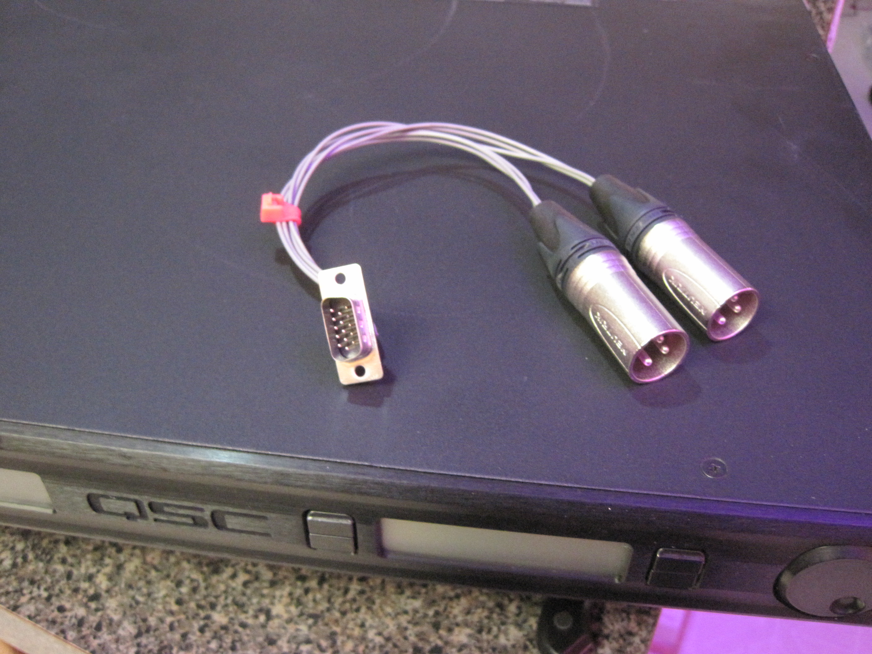
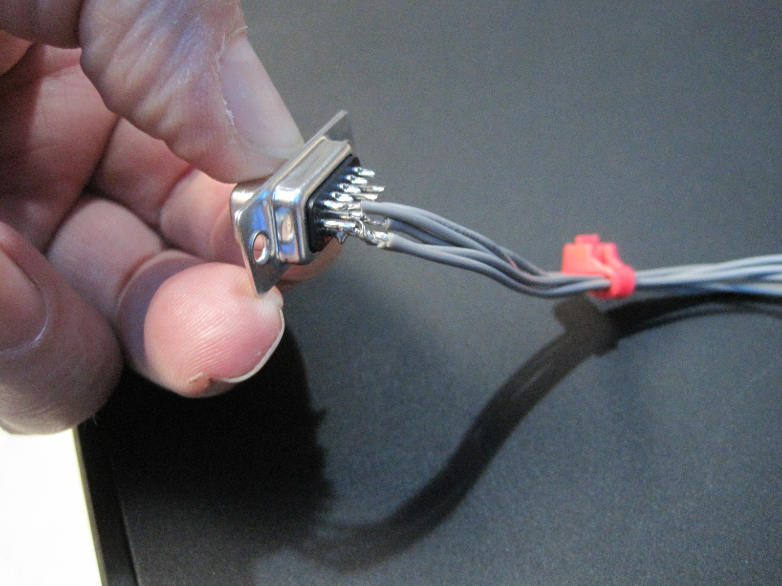
I do plan to try to make fan out cables from the DB-HD-15 connectors on the BASIS units to hook them to 3rd party self amplified PA speakers (the BASIS units I have are meant to only connect straight to QSC amplifiers via the dataport connector on the back, a VGA type cable (that has to have all wires in the cable separate and straight though! Cheap VGA cables not ideal – shared grounds!!))

Also, did I mention, the BASIS units are way cool!!

And in case you came here sniffing around, here is the last versions of the RAVE firmware (Note the topic of this post about bricking units trying to update firmware:
QSC RAVE Firmware Files – The last ones

Adaptive Microsystems ALPHA LED Sign on Lantronix MSS terminal server

Alpha LED Sign

Every few years I pull all this out again, and every few years I’ve forgotten a thing or two and have to poke around figuring things out again after loosing a part or two. MAGFest is soon approaching, and the goal is to ask attendees not to press start on the pinball machines more than one time.

Years ago I picked up some two line LED signs from Adaptive Microsystems. These were used in call centers, at least two from “Mac Warehouse” if anyone remembers that catalog. Probably ACD queue information provided by a middleware solution between the sign and a phone system.

These connect via serial line on a 6 pin RJ-11 (6P6C) cable. The business signs can do RS232 or RS485, while the consumer BetaBrite model can do RS232 only AFAIK.

I bought some Lantronix MSS10 units from eBay dirt cheap years ago when I originally bought these. I used velcro to hold the MSS10 boxes to the back of the signs and made cables to go from the RJ11 serial port to the Lantronix. I then wired in the 5vdc for the Lantronix straight from the power supply on the sign. This way there was only a single power cord and you could plug 10mbps ethernet straight into the sign and feed it data. All this was taken apart when these were located on Granby Street in a project for Art!Everywhere during the 757 Labs Hackerspace days. So I need to put it back together, and I couldn’t find the original cabling from when the term servers were on the signs just when they were hooked to a Livingston ortmaster for the art project.

As time has gone on a lot of pages have come up about the signs, much different than when I first got them. I recommend BB-XML for talking to the signs, it’s amazing. And Walt’s LED sign page.

The pinout to go from a RJ-11 6p6c shell to a DB25 female is:
GREEN to Pin 2
RED to Pin 3
BLUE to Pin 7
This is used with a rollover cable. This is where the two plugs facing each other tip to tip, the wires are the same on both sides (bottom is same color, top is same color.) See Walt’s page for info on this.

The pin full opposite of ground (WHITE) have a +5vdc line from the sign — it needs to be removed or protected from coming into contact with other pins. Insulate or cut the 3 spare pins.

In my old cables I swear I connected CTS to RTS on the host side or something, but I think I got around it this time.

The MSS10 setup should go like this:

Connect via null cable to the serial port:

Username: Whatever
SET PRIV
Password: system
change ipaddress x.x.x.x
change subnet mask 255.x.x.0
change gateway x.x.x.x
change speed 9600
change charsize 8
change stopbits 1
change parity none
change flow control ctsrts
change modem control disabled
change signal check disabled

The MSS10 listens on TCP port 2001

pom.pl :

#!/usr/bin/perl
my $moon = `uname -a`;
print "\0\0\0\0\0\0\0\0\0\0\0\0\0\0\0\0\0\0\0\0\0\0\0\0\001" . "Z" . "00" . "\002" . "AA" . "\x1B" . " t" . "$moon";
print "\004";

./pom.pl | nc 2001

Google Mini 1u Supermicro Server

So I picked up a Google Mini 1u server from a local electronics recycling goldmine-of-old-stuff. I’m not a huge Google fanboy by any means, it’s kind of like self-inflicted spyware — or some sort of trap. But I figured this computer looks cool and it would be fun to re-purpose into other tasks.

The machine is pretty old. 250 watt power supply (Ablecom), Supermicro motherboard that has PCI and PCIe-64 bit slots, and a 3Ghz P4 era CPU as I recall. In the future I can see myself swapping in something faster and more power efficient. But I’m not going to worry about that now.

Someone else provided some instructions about how to reset the BIOS as there was a password on it. It’s two half-moon pads near one of the large ICs near the PCI slots. Thanks for the info, that got rid of the password. I ended up mounting two 1TB disks in the thing, which required buying a 2nd right angle SATA power connector and I have a right angle data cable on the way for good measure.

I used a utility knife to carefully cut across the top front of the sticker that covers the entire top of the computer. This is the one with the google logo. I used a dremel tool to cut a straight slot through the security screws so I could remove them with a normal flat blade screwdriver.

Installing CentOS on the thing was the tough part. With the default BIOS revision of 1.1, it didn’t seem to want to boot off of USB. I burned a CD with the CentOS 7 ISO and the initial boot screen would come up but the OS didn’t seem to load. Memtestx86 from that CD just locked up. This was using an external BD-R drive connected via USB. So I downloaded the version 1.1A revision of the firmware and that added much better handling for USB booting. It did wipe out the custom Google Mini splash screen, though. Once the USB thumb drive was connected it was possible to go into the BIOS and set the removable USB device in the boot order. Note — one of my hard drives had some sort of boot block that just gives a cursor and a freeze so that complicated things a tad. There is a setting to slow the blower down which helps with the noise. It’s not as loud as the 3u Supermicro I have so it isn’t much of an issue to me.

Disks are setup with software RAID. I have a 4 port 3ware left over from an old 757.org server and I contemplated getting a 1u 64bit pci riser card so I could put the 3ware card in, but decided against it. I’ll probably regret this at some point in the future but at least the disk IO will be faster.

In the end, it’s up and running CentOS 7, which is kind of gross. It’s this new systemd that most people seem to dislike and they’re doing everything they can to make it look like Windows. I installed OwnCloud to evaluate it for a personal project but realize it’s not what I need and will revert to a long configuration of Apache + mod_dav + LDAP with 389 Identity Server behind it.

Yamaha C1 Music Computer Laptop

Most vintage computers I fall into. But there was one machine that has been on my radar since I first saw one in a store when I was little. That is the mysterious Yamaha C1 laptop. It’s a 286-12 MHZ laptop that has 11 midi ports and SMPTE time code in and out. I hesitate to call it a laptop because it’s so heavy, and there is no option to battery power it. It feels heavy enough to have a battery in it, but it’s just built fairly sturdy.

I’ve had an eBay trigger setup for a few years, but it mostly triggers on people trying to sell advertisements for the machine or ECUs from Yamaha motorcycles that have C1 in the description. But finally, one came up with books and disks and the original bag, and I bid and snagged it.

The caveat is that it has a functional issue. The unit always says it’s sending video to the external display. There is a dip switch on the rear that switches between the internal LCD, or an external CGA monitor. But in the case of this machine it always says it’s going to the external. So I have to fix this.

In the meantime, I am going to scan all the documentation, archive all the floppies and have already read all of the eproms into files. I’ve also documented the power supply connector, and in the documentation have the pinout for the expansion connector slot (but not the hard drive controller header.) So I will be getting all this info together and posting it for the world at large.

In the meantime — back to the issue of the LCD not working. Randomly, perfect timing, my friend Chris Favreau sent me two huge boxes of Amiga 500 goodies. In this lot was an Amiga 1084S monitor which can do CGA. So I wired the Yamaha over to the Commodore monitor and as I expected, there is no output. I never hear a floppy seek so my suspicion is the computer isn’t booting at all.

It’s been sitting open on the kitchen counter for a good while next to a few other projects getting attention. Last night I started really looking around the motherboard, and something I looked for originally but missed is the case. The green electrolytic capacitors look to have leaked some electrolyte. This means two things. First, the capacitors have probably lost their properties and might be causing the machine to not function properly (I assume they’re noise filtering but not sure.) The second — worse part — is the electrolyte is often corrosive. I think I can see a trace that is damaged by this. So the next step is going to be to replace all of the 47uf 25v green caps with replacements, and if the one trace is indeed bad I’m going to have to jumper it if it goes anywhere important. It looks like it just goes to the expansion interface slot — so if it dead ends at the expansion slot connector it’s not a big deal. But I won’t know until the motherboard has been removed. So. Many. Screws.

In the end I’m glad to have found something that looks like it could be the issue. I heard of someone else with the exact issue (External CRT always no matter switch position, and non functioning perhaps.) Electrolytic caps are probably the #1 failure of all electronics so not totally unexpected.

—[ UPDATE 7/5/2015 ]—

I replaced the 9 x 47uf 25v electrolytic caps that were leaking in the system. I cleaned up the board and tested the traces that looked like they have some corrosion from the leaked electrolyte and they seem to still function. The bad news is the system still seems to not be posting at all. No floppy seek and it’s still stuck saying external CRT when the dip switch is set for internal LCD.

The rear panel dip switch #1, on one side is connected to ground. The other side hits resistor pack PA12 near the keyboard connector, then goes on to IC52 which presumably reads it. So it’s probably read by software.

I sent an email to Yamaha USA asking about schematics. This normally does not work with any large corporation, but we will see. Anyone that has one of these systems working, you’re at risk of damage from capacitors leaking. This system I think was stored sitting upright, so the electrolyte managed to go through the board and run down the back.

Next up is I don’t know. I might look into the inverter stuff for the LCD, the sub-board. I will also wait to hear from Yamaha.

—[ UPDATE 10/2/2015 ]—

Okay this thing has been on the counter too long. I re-capped the LCD inverter board, still no signs of life. There is no disk seek on startup, which makes me think the computer isn’t executing code. I found online someone else talking of having the same issue. I looked at the motherboard more, trying to inspect for damage from the traces that show slight corrosion from the electrolyte leaking. But nothing really stands out.

Another thought that hit my mind is I’ve heard that some EPROMs lose data over long periods of time. So perhaps the BIOS chips are corrupted? It might come down to having to find a working machine to compare. Looking in the data it does appear there could be corruption. The name Phoenix Technologies has the first letter as a C in one ROM, another character in the other. Bitrot might be the issue.

I dug out the o-scope and looking at one of the BIOS EPROMs I see activity on all data lines, all address lines and the OE pin constantly. Not sure if this is normal, since no working unit to compare against. The lack of any normal ISA slot means there is no way to plug in any of the POST code debugging boards that existed for ISA slotted computers of this era.

————————————

Here are some pictures of inside the Yamaha:

View post on imgur.com