Atari 1040ST Overhaul

MAGFest was donated an Atari 1040ST, and I decided to overhaul it to working condition. The Atari ST’s legacy is mostly in the music world, and I have some experience repairing mine.

First up power supply. Blown capacitor on it. Recapped the entire PSU with a kit from an online vendor. All is well.

Second up. She’s golden as movie theater popcorn. Retrobrite time:

Atari 1040ST retrobrite

Lastly, one of the spacebar stabilizers broke during the retrobrite process. I managed to CAD out a replacement in sketchup and printed it. I swear I searched thingiverse before making one but didn’t find one, but apparently I’m not the first. None the less I posted the file from mine on the site as well.

Atari 1040ST keyboard thing

Machine is working and made it to MAGFest 2020.

Atari 1050 Floppy Repairs

Super loads of thanks to the people on AtariAge.com for help on these!

Many moons ago I bought a bunch of Atari 8bit parts from the CHKD Thrift Store in Norfolk. I’m talking 15 years ago or more.

It turned out that all of the floppy drives were bad. I sat one them forever. Sold two for peanuts at the Vintage Computer Festival East, but kept back one that had a Happy 1050 enahancement, and one random one for spare parts just incsae.

So I pop open the Happy equipped drive, since that is cool and I figure that is the one I want to work. When I open the other drive and actually remove the shield around the CPU, I notice there is an ICD US Doubler enhancement installed! Whoot!

One drive had a bad WD IC, which I found by comparing chips. The other drive had an issue where it kept rebooting. I have already forgotten what I fixed. Phew.

The replacement WD chip required that I re-calibrate some things, once again documented on AtariAge.

Post on AtariAge:
http://atariage.com/forums/topic/291001-troubleshooting-1050-w-happy/

Atari 130XE, Bad RAM, Won’t pass memory test. Plus failed keyboard!

Somehow, somewhere I achieved a 2nd Atari 130XE home computer. This is the more advanced version of the first computer that I started on – the Atari 800XL. I really liked the Atari 800XL, it was a sleek computer and looked better than the Commodore 64.

At some point I had a 65XE but can’t seem to find it, but was confused when I found the 130XE that didn’t work. I think maybe my buddy Cyberflux gave it to me — I’m not really sure. Anyways, we can’t have broken stuff taking up space so the idea was to fix it.

RAM Issue

First things first, the machine started up straight into memory test. ROM passes, RAM fails. Most of the RAM fails. I look up videos on youtube, and theirs seemed to have the same crazy pattern with most of the RAM bad. I ordered some replacement chips, and tried a trick I read about of piggybacking a good IC on the bad, walk thru them and find the failed one. That didn’t work for me, I think there was two bad ICs. The chips on the left are the lower 64K so try to fix those first. I used a Hakko 808 to desolder the RAM chips 2 at a time and socket them. I put two new chips in, then moved the other two down. Eventually the last two chips brought the machine to life and it booted straight into basic.

I used a SALT cart to test the RAM. All is good.

But the keyboard….

The keyboard had something spilled in it. The machine looks great from the outside, but keyboard spill damaged the keyboard membrane. This mylar sheet has contacts that mate to the keyboard keys. The mylar looked good, but tested bad. At the edges of the contacts it deteriorated where it’s between two sheets. Repair would be daunting, since there was at least 15 bad spots on the thing:

I contacted BEST Electronics, but didn’t notice the email timely. I bought a replacement (mine is a mitsumi keyboard, however the mylar did not say mitsumi or have a part #?) The replacement was around $30 shipped. It feels less thick than the original which worries me long term, but it works 100%.

With these two things fixed, the 130XE is 100% working.

In the process I also ended up repairing two 1050 floppy drives and built a SDrive-MAX! More on that next posts.

Amiga 2000 / 2500 to VGA using GBS-8200 “Arcade” Scaler

The Commodore Amiga produces RGB video output @ 15khz. It has the ability to run in a higher resolution mode which causes a crazy amount of flicker when the screen refreshes. While I totally respect and give props to the Amiga friends over the years, their monitors seemed to always be a downfall. As a MS-DOS and VGA just didn’t have that issue.

This isn’t a new trick and has done before. But here is some slight documentation. I used one of the scalers that are popular with us arcade people to scale the video to drive a VGA monitor. This is pretty well known, really the most limiting part is getting hold of DB-23 connectors. In my case I used a DB9 as the input so I could re-use the DB-23 to DB-9 monitor cable with the scaler. I have a plastic project box on order from eBay/China to house the scaler and mount the connectors. I was more than impressed by the output from the scaler board, it looks really good.

Quick success and rapid turn around on this!

If you want to do the same using the DB9, I used a DB9 male solder type D-SUB.
Always check the pin labels on the plastic just to double check direction.

Pin 1 = Black, GND
Pin 3 = Red
Pin 4 = Green
Pin 5 = Blue
Pin 7 = Grey = Sync

The Yellow wire is not needed, no connection to the separate HS and VS pins on the scaler board.

Amiga 2500 / scaler

SGI Indigo R4K Failure – Let out the magic smoke! Burning smell

SGI Indigo Failure

So I *finally* managed to find the keyboard cable for my SGI Indigo on my last trip to Norfolk, VA. This completed what I needed: the 13w3 to VGA cable, the special keyboard and mouse, the system and the keyboard interconnect cable. I humped the thing onto my desk after clearing a bit of space, hooked it up to my monitor, then switched my first SGI on. It powered on! But then came this nasty smell. That’s not good! It did show the clock TOD error, no chime sound (just clicks.)

I originally bought the Indigo from Reputable Systems (Greg Douglas) in the 90s. I was working tech support at the time, living with my parents, and it cost a good chunk of cash — especially by todays standards. Originally it was R3K with a lower level graphics subsystem that I believe could do some hardware 3d acceleration but only 256 colors. I’ll admit when I first started messing with it I was a bit disappointed. It was still sort of slow, but had good audio capabilities and worked well as an X-term. It wasn’t long before MP3 was a new thing and the system couldn’t decode a 128kbps MP3 real time though, it took about 6 minutes for a 4 minute song — so I would have to write it out then write it to minidisc. Creative commons licensed music, of course.

Somewhere along the lines in my SGI fandom I think I ended up with a 9u VME frame that had an ELAN graphics boardset on it. I also ended up with a 2nd SGI Indigo from NASA auctions I used to frequent, one with the faster MIPS R4000 series CPU (R4K.) I remember posting that I was giving away a bunch of hardware including parts from the NASA Indigo, and left it and other stuff behind my office in Virginia Beach for someone else to pick up. But a homeless scrapper got to it first, taking everything metal and leaving plastic shards of laser printers and SGI Indigo (and other equipment) behind. Ugh.

But I held onto my Indigo, not having looked at the CPU cards in a long time. The first thing I did was pull out the CPU card and thought, “man this is bulkier than I remember! What a crazy heatsink for this slow R3000 processor.” But it turns out the R3K board isn’t a R3K board, it’s a R4K board. So then I’m thinking, “Okay so I guess I kept the R4K CPU and the lower graphics board.” But no, the graphics boardset looks stout. So I guess I kept both higher end parts and gave away the old R3K / Entry stuff. Or maybe the Entry graphics was in one of the bigger deskside systems on the frame the Elan came on. I can’t remember.

I remember that the Indigo had two power supply options. One for R3K/Elan graphics and one for R4K. I thought you could use a R4K with entry graphics on the weaker power supply as well. This was a huge issue in my mind since I figured my Indigo had the R3K PSU. I pulled the PSU from Indigo (My Indigo was always named Eggbert from a Super Mario Bros 2 character of similar name that was purple, so from here on it’s Eggbert.) So Eggbert’s PSU turns out to be the R4K model! I opened it up, the capacitors look okay but that really doesn’t say much. No burnt smell inside PSU.

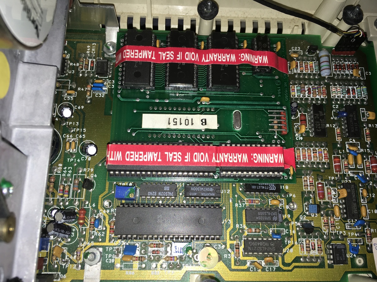
So back to sniffing the circuit boards more. I sniffed and sniffed. Two times over I missed the roasted capacitor on the bottom of the CPU card. I was thinking it had come from the graphics boardset, which sits in the case right next to the bottom of the CPU boardset.

The fried capacitor is C531, and this is near the sound section of the CPU board. No telling what it actually goes to but the lack of the chime sound might have something to do with it. Image slideshow above has a picture of the fried capacitor. Audio sections of computers often use the negative voltages for opamps and DACs where the rest of the computer might not use these voltages, so I might have to check to make sure the power supply isn’t doing something bad on the negative voltage outputs (if it has them.)

In the process of diagnosis I have made a list of all similar style capacitors on the board. I don’t know what is wrong with the machine, but if this style/make of capacitor is degrading from age then the solution should be to replace them. They’re SMD, but pretty large SMD so replacement shouldn’t be TOO bad.

So here is a list of the capacitors I have made so far. I’ve only researched 2 of the 4 with regards to what standard the size is. I have what I believe are DigiKey part numbers for the value that fried and the most common other value (prob used for noise filtering on the power rail.)

I measured the size with a caliper and best guessed on what it equates to in industry.

——————————————

SGI Indigo SMD tantalum caps of the style of the one that burned up:

Top of PCB:
C14, C15, C23, C48 = 47uF,16v
C30 = 33uF, 20v

Bottom of PCB:
C555, C544, C525, C513A, C513B, C578A, C578B, C645A, C645B = 47uF, 16V
C697 = 33uF, 16v
C551 = 33uF, 20V
C507? = 10uF, 10V

C551 is the crispy one

47uF/16v = 7.3mm x 4.42mm : Size 2917 (7343 Metric) / Digikey – 478-1739-1-ND
33uF/20v = 7.44mm x 4.33mm : Size 2917 (7343 Metric) / Digikey – 399-3788-1-ND
10uF/10v = 5.5mm x 3.3mm :
33uF/16v = 7mm x 4.45mm :

———————————————

I will also have to do a battery holder mod since TOD battery is dead.

More updates once replacement caps come in and I replace them.

Yamaha C1 Music Computer Laptop

Most vintage computers I fall into. But there was one machine that has been on my radar since I first saw one in a store when I was little. That is the mysterious Yamaha C1 laptop. It’s a 286-12 MHZ laptop that has 11 midi ports and SMPTE time code in and out. I hesitate to call it a laptop because it’s so heavy, and there is no option to battery power it. It feels heavy enough to have a battery in it, but it’s just built fairly sturdy.

I’ve had an eBay trigger setup for a few years, but it mostly triggers on people trying to sell advertisements for the machine or ECUs from Yamaha motorcycles that have C1 in the description. But finally, one came up with books and disks and the original bag, and I bid and snagged it.

The caveat is that it has a functional issue. The unit always says it’s sending video to the external display. There is a dip switch on the rear that switches between the internal LCD, or an external CGA monitor. But in the case of this machine it always says it’s going to the external. So I have to fix this.

In the meantime, I am going to scan all the documentation, archive all the floppies and have already read all of the eproms into files. I’ve also documented the power supply connector, and in the documentation have the pinout for the expansion connector slot (but not the hard drive controller header.) So I will be getting all this info together and posting it for the world at large.

In the meantime — back to the issue of the LCD not working. Randomly, perfect timing, my friend Chris Favreau sent me two huge boxes of Amiga 500 goodies. In this lot was an Amiga 1084S monitor which can do CGA. So I wired the Yamaha over to the Commodore monitor and as I expected, there is no output. I never hear a floppy seek so my suspicion is the computer isn’t booting at all.

It’s been sitting open on the kitchen counter for a good while next to a few other projects getting attention. Last night I started really looking around the motherboard, and something I looked for originally but missed is the case. The green electrolytic capacitors look to have leaked some electrolyte. This means two things. First, the capacitors have probably lost their properties and might be causing the machine to not function properly (I assume they’re noise filtering but not sure.) The second — worse part — is the electrolyte is often corrosive. I think I can see a trace that is damaged by this. So the next step is going to be to replace all of the 47uf 25v green caps with replacements, and if the one trace is indeed bad I’m going to have to jumper it if it goes anywhere important. It looks like it just goes to the expansion interface slot — so if it dead ends at the expansion slot connector it’s not a big deal. But I won’t know until the motherboard has been removed. So. Many. Screws.

In the end I’m glad to have found something that looks like it could be the issue. I heard of someone else with the exact issue (External CRT always no matter switch position, and non functioning perhaps.) Electrolytic caps are probably the #1 failure of all electronics so not totally unexpected.

—[ UPDATE 7/5/2015 ]—

I replaced the 9 x 47uf 25v electrolytic caps that were leaking in the system. I cleaned up the board and tested the traces that looked like they have some corrosion from the leaked electrolyte and they seem to still function. The bad news is the system still seems to not be posting at all. No floppy seek and it’s still stuck saying external CRT when the dip switch is set for internal LCD.

The rear panel dip switch #1, on one side is connected to ground. The other side hits resistor pack PA12 near the keyboard connector, then goes on to IC52 which presumably reads it. So it’s probably read by software.

I sent an email to Yamaha USA asking about schematics. This normally does not work with any large corporation, but we will see. Anyone that has one of these systems working, you’re at risk of damage from capacitors leaking. This system I think was stored sitting upright, so the electrolyte managed to go through the board and run down the back.

Next up is I don’t know. I might look into the inverter stuff for the LCD, the sub-board. I will also wait to hear from Yamaha.

—[ UPDATE 10/2/2015 ]—

Okay this thing has been on the counter too long. I re-capped the LCD inverter board, still no signs of life. There is no disk seek on startup, which makes me think the computer isn’t executing code. I found online someone else talking of having the same issue. I looked at the motherboard more, trying to inspect for damage from the traces that show slight corrosion from the electrolyte leaking. But nothing really stands out.

Another thought that hit my mind is I’ve heard that some EPROMs lose data over long periods of time. So perhaps the BIOS chips are corrupted? It might come down to having to find a working machine to compare. Looking in the data it does appear there could be corruption. The name Phoenix Technologies has the first letter as a C in one ROM, another character in the other. Bitrot might be the issue.

I dug out the o-scope and looking at one of the BIOS EPROMs I see activity on all data lines, all address lines and the OE pin constantly. Not sure if this is normal, since no working unit to compare against. The lack of any normal ISA slot means there is no way to plug in any of the POST code debugging boards that existed for ISA slotted computers of this era.

————————————

Here are some pictures of inside the Yamaha:

View post on imgur.com